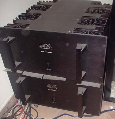
Announcement

Collapse
No announcement yet.

D.I.Y.ตอน ต่อแอมป์ 40+40 w. ราคาไม่ถึงพัน

Collapse
X
 
  • Filter
  • Time
  • Show
Clear All
new posts

  • PCB ส่ง ซีเกต นี่ วาดลงกระดาษ A4 ให้เขาได้ไหม

    ราคาจะเท่ากับ ส่ง เป็น PDF ไหมครับ

    Comment


    • ผมก็มึนๆ - -. เมื่อเช้า เมาเวลาอย่างแรง

      จะเป็นแบบนี้ได้
      dsp>>dac>>adc>>spdif>>>d3
      ค่อนข้างยาก เพราะ line out ที่ออกจากdac มันต้องเชื่อมกับ line in ของadc (ไม่น่าจะเชื่อมอยู่ ยกเว้นแต่ต่อสายจากแจ็คด้านหลังเข้าหากันเอง)
      (ลองเปิด หน้าrecordingของsound ดูก็ได้ ว่ากราฟมีอันไหนขึ้นลงมั้ย เว้นwave เพราะ wave มันจับสัญญาณดิจิตอลในเครื่อง)

      driver creativeไม่รู้มัน มีแอบทำอะไรรึเปล่า คิดว่าเป็นเรื่องmixer อยากเห็นหน้า console ของx-fiด้วยว่าปรับไว้ยังไง
      เป็นไปได้ ว่า ถ้าเลือก speaker คือ ผ่าน mixerของdriver ถ้าเลือกspdif คือโหมดpassthrought

      Comment


      • PCB ส่ง ซีเกต นี่ วาดลงกระดาษ A4

        ได้ครับ... ราคาน่าจะเท่านะ


        ผมก็ใช้วาด llustrator ...ไป...ผมเขาก็ต้องไปทำแผ่นฟิล์ม...อยู่ดี...

        ให้ดี ถ้ามีปริ๊น...leser ก็..ปริ๊น..กระดาษไข..

        ไปเลย...เขาแบบใช้กลับฟิล์ม / ก็คือ เส้นดำ กลับเป็นขาว...

        จะได้ไม่ต้องเสียค่า....ฟิล์ม...30 บ.

        ตอนหลังผมก็...ปริ๊น.ให้ไปเลย...ประหย้ดเงินนะถ้าทำหลายแบบ...
        Last edited by jinn; 11 Aug 2011, 13:38:51.

        Comment


        • คิดง่ายๆแค่ว่าคุณจะให้ DAC ซ้อน DAC ได้คุณต้องส่ง Analog ไปให้ Fiio แต่ในที่นี้ต่อสาย digital coax เป็นอันว่าจบทฤษฎีไปได้เลย
          ดูแค่อินทอเฟสก็รู้แล้วไม่ต้องไปงงกับ DSP,DAC,ADC,windows mixer เลย เรามาโฟกัสตรงจุดที่ว่า "ทำไมเสียงเปลี่ยน" กันดีกว่า

          Comment


          • โพสไว้ที่กระทู้นึง ก็อปมาแปะไว้นี่ด้วยดีกว่า

            Mark Levinson ML-2 class-a mono block power amps , 20watts/channel
            ผลิต1977-1986


            ตัวละแชนแนล แชนแนลละแค่20วัตต์เองครับ
            ขับลำโพงได้หมดทุกตัว แม้กระทั่งลำโพงยี่ห้อWilson Audio รุ่นWAMM


            Wilson Audio WAMM
            Wilson Audio manufactured the Wamm for a record breaking 25 years, I was told the last pair was manufactured in year 2002. There are a total 53 pairs of Wilson Audio Wamm speakers in use world wide.

            - ตอนนู้นเคยถามเจ้าของลำโพงชุดนี้ เค้าบอกว่าเท่าที่รู้ ในไทยน่าจะมี2ชุด
            - สมัยนู้น ในเมกาใครซื้อรุ่นนี้ จะมีจนท.ของWilson Audioตามไปเซ็ทลำโพงให้ด้วย แต่ในไทยไม่เห็นเค้ามาเซ็ทให้
            - ลองสังเกตุรูปดีๆ ที่พื้นจะมีการมาร์คเครื่องหมายไว้ที่ฐานลำโพงด้วย เซ็ทตำแหน่งเข้าที่เข้าทางก็มาร์คเอาไว้เลย เพราะจนท.เค้ามาทำให้แค่ครั้งเดียว


            18 inch bass driver, in a large ported enclosure


            External power supply boxes กับ parametric EQ and electronic x-over
            ( Wilson Audio Wamm speaker package )


            เมื่อก่อนที่เคยโพสลงกระทู้ ที่บอกว่าฟังแผ่นเสียงThe Wall แล้วเสียงเฮลิคอปเตอร์กับเสียงตาวอลเตอร์อยู่เหนือหัวจริงๆ ก็จากชุดML-2 2ชุด + WAMMนี่แหล่ะ
            Last edited by keang; 11 Aug 2011, 15:37:16.

            Comment


            • พูดถึง DAC ที่กำลังดูกัน ก่อนอื่นดูก่อนว่า เวลาเล่นยังปรับเพิ่ม/ลดVolume จากในWindows ได้อยู่หรือไม่
              ถ้าได้และอยากดูว่าจุดไหนทำให้เสียงเปลี่ยน ก็ดูว่าDeviceตัวไหนที่เราปรับเพิ่ม/ลดVolume จากในWindows ได้
              ก็ตัวนั้นละครับ เพราะการปรับVolume แบบDigital จะใช้การเปลี่ยนแปลงที่ตัวสัญญาณ
              ทำได้หลายแบบ/วิธีอยู่น่ะ ลองถามอากู๋ดู

              Comment


              • 0460 ต่อ จั๊มเปอร์ spdif > coax> fiio d3 > 2RCA to 2RCA > amp
                เปิดด้วยโหมด Speaker สามารถปรับแต่งเพิ่ม-ลดเหมือนโหมด Speaker ปกติ (แต่ไม่สมบูรณ์)
                เสียงออกมาเป็นแนวเสียงเดียวกับโหมด Speaker ปกติที่ต่อด้วยสาย Analog
                ตรงนี้ครับที่มึน ....ว่ามันมีการทำงานลักษณะไหน
                -------------
                0460 ต่อ จั๊มเปอร์ spdif > coax> fiio d3 > 2RCA to 2RCA > amp
                เปิดด้วยโหมด SPD/IF out เสียงผิดกับอนาล็อคปกติ เสียงเป็นของ fiio d3 แน่นอน
                เป็นการทำงานปกติ....ตรงนี้ไม่มีข้อสงสัยครับ

                Comment


                • เครดิต : diyAudioProjects.com


                  NP-100v12: 12AU7 (ECC82) / IRF510 Headphone Amp


                  12AU7 (ECC82) Tube Pinout Diagram


                  circuit


                  A Bipolar Junction Transistor (BJT) can be used in place of the MOSFET, but MOSFETs tend to be more stable with temperature and current shifts. Use caution when handling MOSFETs as they are very static sensitive.

                  The signal enters the grid via a coupling capacitor, it leaves the plate (anode) amplified and 180 degrees out of phase, it is then directly coupled to the gate of the MOSFET and leaves the source. The signal is then coupled to the headphones via a electrolytic capacitor, which blocks the DC from your headphones. Since the sleeve of your headphones is common it completes the circuit.

                  The MOSFET is biased into class-A operation and will be constantly conducting at approximately 125 mA. The LM317 regulator is configured as a constant current source and regulates at 125 mA in the given configuration. You can use the online LM317 regulator calculator to determine the current through the regulator by adjusting the program resistor. It is suggested that a 10 ohm 1/2W program resistors is used for R4 (you can use two 1/4W 20 ohm resistors in parallel). Note that the regulator and MOSFET devices will heat up and radiate heat. There are some real in depth calculations for heat, but know that the MOSFET can dissipate at least 1.6 Watts and the LM317 2 Watts to air, at room temp. I tested a prototype over a continuous 24 hours period in a 150 cubic-centimeter (about 9 cubic-inch) enclosure and there were no thermal stability issues. You can add heatsinks to the devices, just ensure that if you gang the FETs together to use mica and silicone washers to prevent the 12V supply from transferring to the heat sinks.

                  The schematic above shows only one channel, you will have to wire the the tube for both channels using different pins. The only wiring that is common for the 12AU7 tube between the two channels is the heater.


                  PCB Files
                  > NP-100v12 PCB Image - (PNG 50kB)
                  > NP-100v12 Components-Layout - (PNG 23kB)
                  > NP-100v12 PCB Image - (PDF 13kB)
                  > NP-100v12 EAGLE Circuit Board File - (BRD 16kB)
                  > Potentiometer Routing PCB Image - (PDF 3kB)
                  > Potentiometer Routing EAGLE Circuit Board File - (BRD 5kB)


                  เห็นหลายคนพูดถึงอยากให้มีDIY Group Buyในเวปนี้กัน ผมว่าตัวนี้ก็น่าสนใจไม่น้อยน่ะ
                  ถ้าจะทำDIY Group Buyกันจริงๆ ตั้งกระทู้ใหม่ แล้วพูดคุยกันในนั้นได้เลย


                  เค้าเริ่มทำตั้งแต่ปี2008 ปรับปรุงล่าสุดapril 2010
                  วงจรใช้ไฟแค่12โวลท์ เอาไปใส่Sound Cardก็ได้ หรือ ใส่ในเคสเครื่องคอมก็ได้ หรือ ทำแบบExternalก็ได้
                  ไฟล์PCBก็มีให้ครบทุกอย่าง หรือที่เค้าทำมาไม่ถูกใจ จะเขียนPCBใหม่ ในเวปก็มีคนทำได้หลายคน
                  ตัววงจรก็ยังสามารถปรับปรุงต่อยอดได้อีก ยังโมเพิ่มได้อีก
                  Last edited by keang; 11 Aug 2011, 23:20:30.

                  Comment


                  • DIY Group Buyกันจริงๆ ...ผมว่าเป็นประโยชน์มาก...สำหรับมือใหม่....

                    ที่มีความสนใจแต่...ยังไม่รู้จะเริ่มต้นยังไง...ผมว่าที่มีนำ้ใจ...แบ่งปันความรู้กันได้เสมอ...

                    ลงชื่อ.....เอาด้วยครับ....
                    Last edited by jinn; 11 Aug 2011, 23:38:49.

                    Comment


                    • DIY Speaker / Amplifier Dummy Load

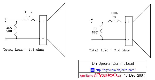
                      This is a simple DIY Speaker dummy load that I put together quickly. After constructing an AMP6 T-Amp, I was testing the maximum power output using a 4.7 ohm ceramic power resistor. I somehow got distracted and before I knew it, I could smell burning. The ceramic resistor had started burning through a floor mat and melting the insulation of the test leads which had fallen on the hot resistor. So rather than test with loose resistors and test leads, I figured I should make a properly enclosed dummy load.

                      Rather than just using a load resistor across an amp, I prefer to be able to hear what is going on during testing. The schematic below shows two dummy loads. With a speaker connected, the amplifier will see either a 4.3 or 7.4 ohm load while the attached speaker will receive less than about 1% of the output power. You can check the net load for yourself by following the basic electronics formulas. With a simple setup like this you can test at high power without risking damaging speakers, going deaf or driving other people crazy. If a speaker is not connected to the dummy load, the amplifier will see either a 4.5 or 8 ohm load.


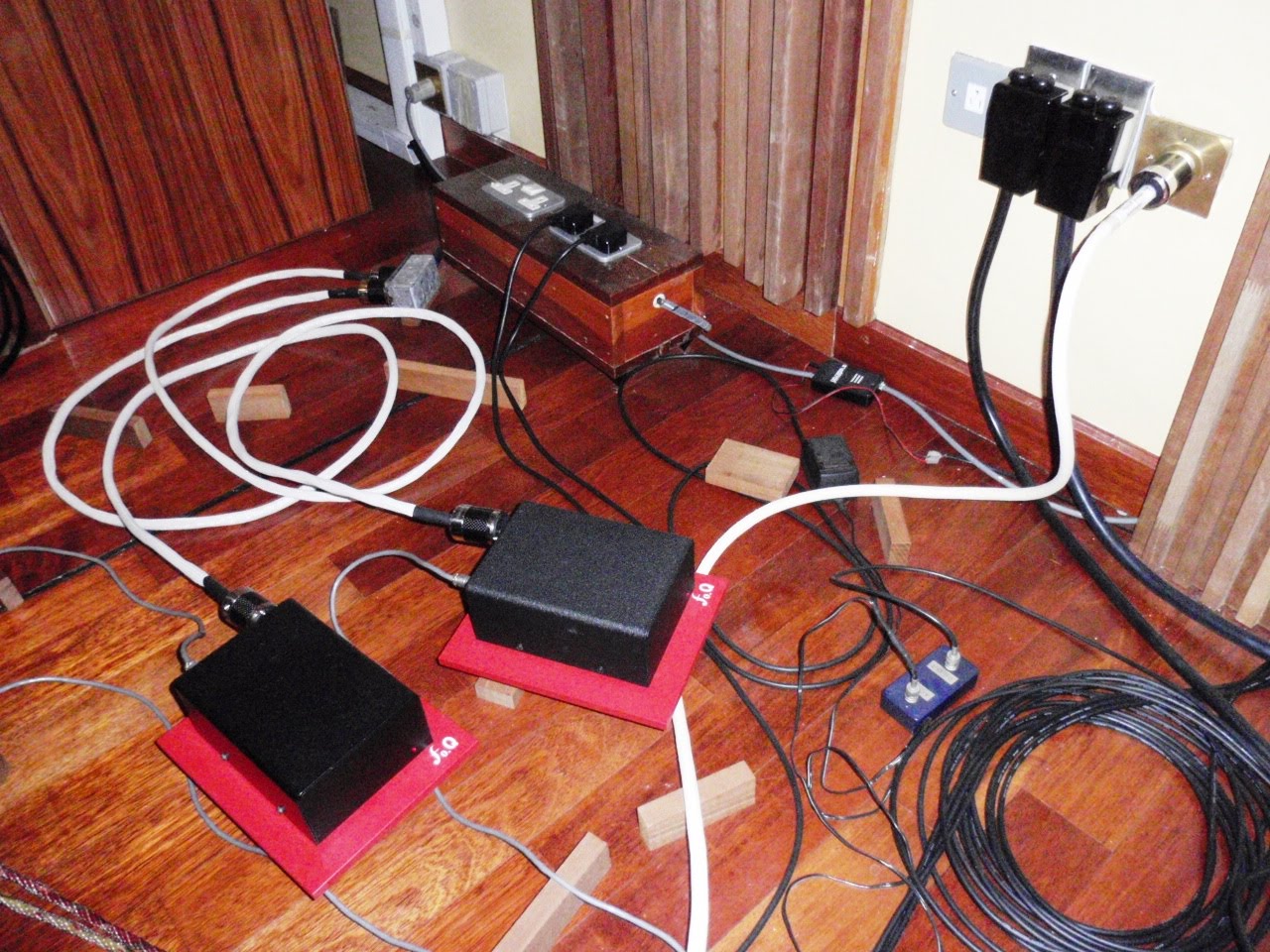
                      The two dummy speaker loads are housed in the same type of aluminum baking pan that I used for my 50EH5 Single Ended Tube Amplifier. To help promote cooling, I mounted the 50W resistors to heat sinks that had been salvaged from dead computer power supplies. The 4.5 ohm resistor is attached to the larger heat sink. The aluminum enclosure also helps dissipate some heat from the resistors. Since the resistors are cooled somewhat, it is ok to apply more than 50W of power for a very SHORT period of time, but don't get carried away.


                      I used binding posts to allow for easy connection to and from the dummy load. The binding posts also make it easy to add a small capacitor or inductor if you want to try different load scenarios when testing an amplifier.

                      Comment


                      • Originally posted by keang View Post


                        เห็นหลายคนพูดถึงอยากให้มีDIY Group Buyในเวปนี้กัน ผมว่าตัวนี้ก็น่าสนใจไม่น้อยน่ะ
                        ถ้าจะทำDIY Group Buyกันจริงๆ ตั้งกระทู้ใหม่ แล้วพูดคุยกันในนั้นได้เลย


                        เค้าเริ่มทำตั้งแต่ปี2008 ปรับปรุงล่าสุดapril 2010
                        วงจรใช้ไฟแค่12โวลท์ เอาไปใส่Sound Cardก็ได้ หรือ ใส่ในเคสเครื่องคอมก็ได้ หรือ ทำแบบExternalก็ได้
                        ไฟล์PCBก็มีให้ครบทุกอย่าง หรือที่เค้าทำมาไม่ถูกใจ จะเขียนPCBใหม่ ในเวปก็มีคนทำได้หลายคน
                        ตัววงจรก็ยังสามารถปรับปรุงต่อยอดได้อีก ยังโมเพิ่มได้อีก
                        ขอบคุณมากครับ ...กำลังสนใจว่าจะต่อ ปรี 12au7 อยู่เลยครับ
                        ที่เค้าเอาไปโมใส่ซาวน์การ์ด ..ผมเห็นจุดบกพร่อง 4 จุด
                        แต่ไม่อยากทัก
                        1 นำหนัก..กับบาลานซ์ อาจทำให้เกิดปัญหากับ PCBหรือ slot ได้
                        2.ความร้อนสะสม ภายในเคสที่เพิ่มมากขึ้น
                        3.ระบบไฟ
                        4. 2 ชาแนล กับใช้แค่หลอดเดียว 1 หลอดต่อ 1ชาแนลจให้เสียงที่ดีกว่า
                        ----------------
                        เท่าที่มองคร่าว ๆลักษณะทางเดิน น่าจะเป็นหลัง opamp ก่อนออกอินพุท
                        ถ้าใช่ตามนั้น ...ก็มีค่าเท่ากับ ปรีหลอดด้านนอก
                        ยิ่งเคยเห็นท่านพ่อมด บอกว่า ปรี 12au7 แมท กับ GC ยิ่งอยากทำเลย
                        แต่ตอนนี้ไม่มีอะไรเสร็จเป็นชิ้น..เป็นอันเลย...555+
                        Last edited by tiger X-fi; 12 Aug 2011, 00:13:59.

                        Comment


                        • เพิ่มเติม....

                          NP-100v12 - 12AU7 / IRF510 HeadAmp Support Thread

                          http://diyaudioprojects.com/Forum/vi...hp?f=10&t=1799

                          Power Supply Filtering of unregulated power supplies (linear and SMPS) - 23 Nov 2010

                          http://diyaudioprojects.com/Forum/vi...p=20498#p20498

                          โมสวย...ได้เลย...

                          VALVE HEADPHONE AMPLIFIER


                          http://www.homebuilthifi.com/project/174
                          Last edited by jinn; 12 Aug 2011, 00:28:04.

                          Comment


                          • 1 นำหนัก..กับบาลานซ์ อาจทำให้เกิดปัญหากับ PCBหรือ slot ได้
                            2.ความร้อนสะสม ภายในเคสที่เพิ่มมากขึ้น
                            3.ระบบไฟ
                            4. 2 ชาแนล กับใช้แค่หลอดเดียว 1 หลอดต่อ 1ชาแนลจให้เสียงที่ดีกว่า
                            ข้อ1 ผมว่าเดี๊ยวผู้ผลิตเขาคงแก้น่ะ ดูทรงแล้วติดเคสแน่ๆ

                            2กับ4 ไม่พูดละกัน ไม่เคยลองหลอดไม่รู้มีผลแค่ไหน

                            เรื่องระบบไฟ ผมก็กำลังเอามือกายหน้าผากคิดอยู่ ตัวdsถ้าจั้มไฟให้ใช้จากภาย (ทำได้ทั้ง5v และ+-12v ส่วน3.3volt ยังหาทางเดินมันไม่ค่อยเจอ)
                            มันก็พอทำได้ แต่ตัวมันจะใหญ่ขึ้นอีก +ใช้งานยุ่งยาก (ไม่งั้นจะออกแบบยากแทน เพราะเปิดปิดคงต้องแยกสวิทช์ ไม่งั้นต้องหาทางจั้มไปใช้วงจรpower goodของสายไฟเมนบอร์ดอีก)


                            - -. ทำอะคิดวิธีพอได้ ไม่รู้ปฎิบัติจะรอดมั้ย แต่ทำเสร็จออกมา เกิดอยากจะขายต่อมาด้วยความใหญ่+ใช้งานยุ่งยากคนจะอยากซื้อกันมั้ย
                            เพราะอาจจะไม่เก็บไว้เอง ทำทดลอง-ศึกษาเฉยๆ

                            ผมว่าผู้ผลิตก็คงติดปัญหาเดียว ทำออกมาใหญ่ๆ ใช้ยาก คนมันจะซื้อมั้ย
                            Last edited by ManiacMaew; 12 Aug 2011, 00:34:47.

                            Comment


                            • LM317T
                              ตัว T ต่อท้าย หมายความว่าอะไรครับ?

                              Comment


                              • หลอดเบอร์ 12au7 แนวเสียงเป็นยังไงหรอครับ ผมเคยใช้ 12ax7 กับ 12at7 ครับ แต่ตอนนี้ผมใช้ 12at7 ของ GE แนวเสียงผมชอบมากๆเลยใสบางและ เสียงร้องดี เบสก็นุ่มลอยๆดี

                                Comment

                                Working...
                                X