Announcement

Collapse
No announcement yet.

D.I.Y.ตอน เครื่องขยายเสียง

Collapse
X
 
  • Filter
  • Time
  • Show
Clear All
new posts

  • D.I.Y.ตอน เครื่องขยายเสียง

    D.I.Y by OCZ member

    12AT7 headphone amp by tiger x-Fi

    ---------------
    cmoy single opamp by tiger x-Fi

    ---------------------------
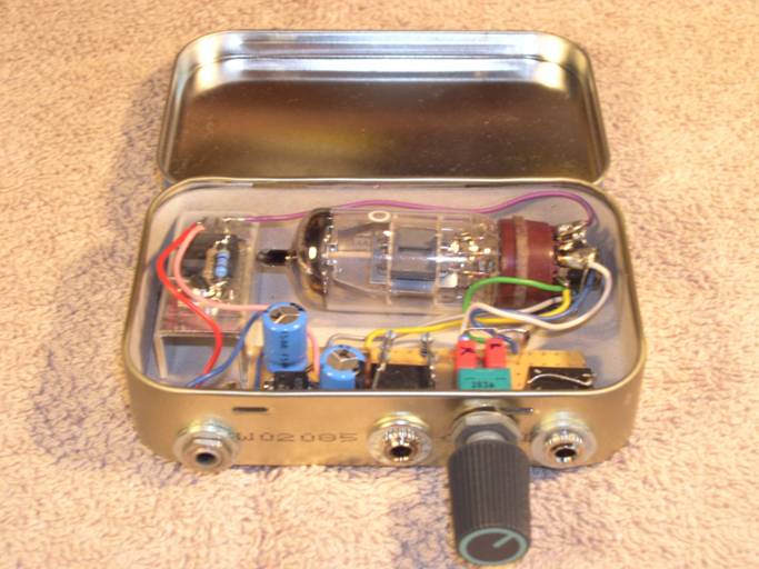
    The Homebrew 6DJ8 Single Tube Headphone Project BY jinn

    ---------------
    Tube Buffer by tiger x-Fi

    -------------------
    dual opamp Headphone by ManiacMaew

    ---------------------
    emitter follower single end by ManiacMaew

    ---------------------
    Regulator 0-30V 2A by IC 723 & 2N3055 by jinn

    --------------------
    Little Elephant Amp. (For Elephant Sp-011 Speaker) by dracoV

    ----------------------------------
    LM1875 Amplifier by dracoV
    -----------------------------
    LM1875 by ManiacMaew

    ------------------
    lm3886 x3 -pre-dac by tiger x-fi

    -------------
    8b8 SE by NoKt

    ---------------

    LM4780 Chipamp ิัิby dracoV

    -----------------
    3886+12AU7 by tumd

    ---------------
    LM3886 x2 parallel by tumd

    ---------------
    LM3886 x2 parallel v.2 by tumd

    ------------
    Pre Op-Amp by tumd

    ------------
    PCM2704 + MOSFET 60W by carbon_za

    -------------
    REPORT no.1 on ecc88/6dj8 pre-amplifier test

    --------------
    แบบ PCB
    dual op amp headphone amp by ManiacMaew
    ------------------------------------
    723 Shunt Regulator
    -----------------------------
    discrete regulator by dracoV


    สาย 3X6 sq.mm by KOTONOHA


    Transistor regulator by tiger x-Fi

    โม OCZ 600W by KOTONOHA
    Last edited by tiger X-fi; 17 Nov 2014, 01:33:07.

  • #2
    TDA7265 by tumd

    --------------
    LM3875 by wutnaja

    ---------------

    DIY ล่าสุด ทำเพาเวอร์ 5V 3A by tumd
    Last edited by tiger X-fi; 20 Jul 2015, 00:13:21.

    Comment


    • #3
      Calculator

      Low-Pass and High-Pass RC Filter Frequency Calculator-Simple R-C Filter Cutoff

      LED calculator- single LED

      LM 317 Calculator


      LM317 Current Calculator

      Zener Diode Calculator

      LINEAR POWER SUPPLY DESIGN ASSISTANT

      Coupling Capacitor Calculator

      Voltage Drop Calculator

      Calculator เกี่ยวกับหลอด

      Triode Calculator

      voltage divider calculator

      Filter Design and Analysis

      Capacitor Charge (Charging) Calculator

      Capacitor Discharge Calculator

      Capacitor Impedance Calculator

      Inductor Impedance Calculator

      Speaker Zobel / Impedance Equalization Circuit Calculator
      Originally posted by keang View Post
      โปรแกรมช่วยคำนวนค่าอะหลั่ยในวงจรเรคกูเลเตอร์แบบใช้ไอซีสำเร็จรูป

      Regulator Design 1.3 > download
      - LM317 (LM150 , LM350) voltage regulator
      - LM317 (LM150 , LM350) current regulator
      - L200 voltage and/or current regulator
      - TL431 precision shunt regulator
      - TL431 precision shunt regulator (with LM317)
      - M5237 3-terminal adjustable regulator
      - 78xx series voltage regulator
      - 78xx series current regulator
      - uA723 precision voltage and/or current regulator
      เว็ปช้างเผือก ตัวช่วยคำนวนหลากหลาย
      -----------------
      ความรู้เบื้องต้น-ที่ควรศึกษา

      ทฤษฎีไฟฟ้าเบื้องต้น - กรมประชาสัมพันธ์

      คู่มือการใช้งาน-Handbook of Operational Amplifier Applications

      วิธีทำงานหลอดสุญญากาศ-How Vacuum Tubes Work


      วงจรแบ่งแรงดันไฟฟ้า

      Voltage divider

      อธิบายหลักการทำงาน isolate signal ground by dracoV

      electron Tube Data sheets

      Power Amplifier Circuit

      Voltage Regulator Circuit
      -----------------------
      แนวเสียงอะไหล่ แบบคร่าวๆ
      bennic pmtกับ xpp by ManiacMaew

      12ax7 Mullard /svetlana /Shuguang by tiger x-fi

      diode vishay VS-15ETL06 by ManiacMaew

      [mini review capacitor] by ManiacMaew

      [MINI review]
      หลอด ecc88 RSD vs e88cc genalex/gold lion by ManiacMaew

      -------------
      วิธีดูขั่ว electrolytic capacitor แบบหางหนู

      tube-buffer


      Lessons In Electric Circuits 1-6
      -------------
      พื้นฐานการกำหนดการทำงานหลอด Triode

      พื้นฐานการกำหนดการทำงานทรานซิสเตอร์ในวงจรขยายสัญญาณ
      --------------------------
      ความรู้เบื้องต้นเกี่ยวกับ op-amp

      op-amp Connection Diagrams


      โครงสร้างหลักวงจรพื้นฐาน
      725px-Opamp-differential.svg.png

      Operational amplifier high pass filter
      The simplest circuit high pass filter circuit using an operational amplifier can be achieved by placing a capacitor in series with one of the resistors in the amplifier circuit as shown. The capacitor reactance increases as the frequency falls, and as a result this forms a CR low pass filter providing a roll off of 6 dB per octave. The cut off frequency or break point of the filter can be calculated very easily by working out the frequency at which the reactance of the capacitor equals the resistance of the resistor. This can be achieved using the formula:

      Xc = 1 / 2 pi f C

      where:
      Xc is the capacitive reactance in ohms
      pi is the greek letter and equal to 3.142
      f is the frequency in Hertz
      C is the capacitance in Farads


      เครดิต http://www.radio-electronics.com/inf...passfilter.php
      -----------------

      Operational Amplifier / Op Amp Gain
      Inverting op-amp gain

      The circuit for the inverting op-amp circuit is shown below. This circuit has the output 180 degrees out of phase with the input and also provides a virtual earth input.


      Basic inverting operational amplifier circuit

      It is easy to derive the calculation for the op-amp gain. The input to the op-amp itself draws no current and this means that the current flowing in the resistors R1 and R2 is the same. Using ohms law Vout /R2 = -Vin/R1. Hence the voltage gain of the circuit Av can be taken as:

      Av = - R2 / R1


      As an example, an amplifier requiring a gain of ten could be built by making R2 47 k ohms and R1 4.7 k ohms.

      Non-Inverting Op-Amp gain

      The circuit for the non-inverting op-amp is shown below. It offers a higher input impedance than the inverting opamp circuit.


      Basic non-inverting operational amplifier circuit

      The gain of the non-inverting circuit for the operational amplifier is easy to determine. The calculation hinges around the fact that the voltage at both inputs is the same. This arises from the fact that the gain of the amplifier is exceedingly high. If the output of the circuit remains within the supply rails of the amplifier, then the output voltage divided by the gain means that there is virtually no difference between the two inputs.

      As the input to the op-amp draws no current this means that the current flowing in the resistors R1 and R2 is the same. The voltage at the inverting input is formed from a potential divider consisting of R1 and R2, and as the voltage at both inputs is the same, the voltage at the inverting input must be the same as that at the non-inverting input. This means that Vin = Vout x R1 / (R1 + R2)Hence the voltage gain of the circuit Av can be taken as:

      Av = 1 + R2 / R1


      As an example, an amplifier requiring a gain of eleven could be built by making R2 47 k ohms and R1 4.7 k ohms.

      Op-amp gain or opamp gain is very easy to determine. The gain calculations for the different circuits is slightly different, but essentially both circuits are able to offer similar levels of gain, although the resistor values will not be the same for the same levels of op amp gain.

      เครดิต http://www.radio-electronics.com/inf...ifier-gain.php
      -----------------
      HOW TO READ CIRCUIT DIAGRAMS


      ---------------------
      cmoy single opamp

      cmoy-single-amp.gif

      Last edited by tiger X-fi; 15 Dec 2014, 00:21:59.

      Comment


      • #4
        คุณเสือเปิดกระทู้ให้แล้ว ฮา ดีจะได้ไม่ต้องจัดหน้าแรกเอง
        -------

        คุยกันบ้างครั้งอาจจะเหมือนเถียงกันหน่อยน่ะ ให้ถือว่าเป็นเรื่องปรกติแลกเปลี่ยนความรู้-มุมมองกัน

        -------
        เอาเรื่องcmoyก่อนน่ะ ง่ายดี

        ผมไม่ค่อยชอบเรียกcmoyเท่าไร บางคนพอเห็นวงจรnon-invertเองก็เรียกcmoyหมด ทั้งทีมีมาตั้งแต่ไหนแล้ว ตามdatasheetก็มี

        ในบทความของchu moy เขาใช้high pass filterแบบนี้


        จะต่างกับแบบที่คุณเสือ โพสด้านบนหน่อย แต่ก็high pass filter เหมือนกัน

        ภาคจ่ายไฟแบบ R spiltter


        ในลิ้งค์จะมีส่วนเพิ่มเติมอีก ใครสนใจลองไปอ่านดู
        credit : http://gilmore2.chem.northwestern.ed...=cmoy2_prj.htm

        ------

        ส่วนนี้ไว้สำหรับคนซน ใครว่ายากไปก็ข้ามไป
        ทำความเข้าใจพื้นฐานมันก่อน ต่อไปก็จะดัดแปลงแก้ไขมันได้ง่าย


        วิธีคำนวณgainก็แบบnon-invert ธรรมดาดูโพสท์บนของคุณเสือได้

        ส่วนวิธีคำนวณหาจุด frequency roll offจะเป็นแบบนี้

        มันจะสัมพันธ์กับCinput และ Rinput ที่อยู่ต่อจากc

        credit: http://www.electronics-tutorials.ws/.../filter_6.html เว็บนี้อ่านง่ายดี(ดูรูป กับสูตรบ้างอันก็พอจะทำความเข้าใจได้แล้ว ตรงไหนยากไปก็ข้ามๆไปก่อน )

        รู้2จุดนี้เราก็พอแก้ไข จุดfrequency roll off กับ gainได้นิดหน่อยแล้ว
        ทำจริงจะต้องลองเองอีกทีด้วย เพราะค่าR พวกนี้มีผลต่อพวก input impedance +op-amp แต่ละตัวต้องการค่าอาจจะไม่เท่ากัน
        (ขี้เกียจลอง ก็searchดูวงจรใกล้เคียงกันเข้าใช่ Rค่าเท่าไร)

        แล้วก็ พอgain ต่ำๆแล้วความเสถียรอาจจะต่ำลงด้วย อาจะต้องปรับค่าr ชดเชย
        ลองหาพวก วงจรส่วนI/V buffer ของdac หรือ วงจรgainต่ำ แล้วเทียบค่าดูเป็นแนวทาง

        --------

        หลักการวางเลย์เอาท์ของcmoyในส่วนของสัญญาณ ขออ้างอิง ของ tpa6120ละกัน

        ถึงเป็นวงจรinvert แต่ก็น่าจะเอาประยุกต์ใช้ได้กับตัวอื่นได้


        เบื้องต้นของเรื่องop-amp เอาไปประยุกต์ใช้กับอย่างอื่นได้อีก ไม่ใช่แค่แอมป์หูฟัง
        พวกวงจรในsound card , ลำโพงคอม, chip amp , dvd player บลาๆ

        แต่อาจจะไปเจอวงจรแบบอื่นที่ไม่ใช่high passแบบที่ยกมา ก็ต้องหาข้อมูลเพิ่มกันหน่อย
        Last edited by ManiacMaew; 13 Apr 2012, 14:28:08.

        Comment


        • #5
          ว่าด้วยภาคจ่ายไฟ
          แบบR2spiltterธรรมดา

          Virtual Ground ? This is the most generic term for any circuit or configuration that creates or synthesizes a ground. It could be just 2 passive resistors as shown in the diagram to the right. Here a single battery is divided by two resistors forming a midpoint that can be used as a virtual ground. This is done in many low cost, low power op amp circuits and can work reasonably well where the maximum currents are less than a few milliamps. The more current you need, the lower the resistor values have to be, and the more power is wasted as heat. It?s ?good enough? for certain applications and widely used.
          credit: http://nwavguy.blogspot.com/2011/05/...nnel-amps.html


          The two 4.7?k? resistors create a ?virtual ground.? Let?s say there?s 12?V across this circuit. The resistors are an 0.5? resistive divider: there is 6?V at the midpoint of the divider. The ?distance? between the midpoint of the divider and the negative side of the power supply is -6?V and the distance to the positive side of the power supply is +6?V. Voil?, two equal but opposite voltages from a single power supply!
          credit: http://tangentsoft.net/elec/vgrounds.html เว็บนี้ก็อ่านง่าย

          ข้อดี ใช้อะไหล่น้อยประหยัดทั้งพื้นที่และเงิน
          ข้อเสียจ่ายกระแสได้น้อย ไม่ค่อยstable(macthค่า rด้วยก็ดี)
          ถ้าอยากให้จ่ายกระแสได้เพิ่มขึ้นก็จะลดค่าRลง แต่จะเปลืองไฟขึ้นกว่าปรกติ เพราะ rมาต่อคร่อมลงขั้วลบแบต เท่ากับว่า ช่วงที่โหลดไม่ได้กินไฟอยู่ แต่r splitterยังกินไฟอยู่

          ตามไปอ่านใน2เว็บข้างบนจะบอกวิธีทำvirtual groundแบบอื่นอีก

          พักก่อนค่อยมาต่อ
          Last edited by ManiacMaew; 13 Apr 2012, 15:00:48.

          Comment


          • #6
            ^
            ดีครับ ..เดี๋ยวพยามจัดหมวดหมู่ให้หาขข้อมูลง่ายครับ

            Comment


            • #7
              ช่วงแรกลงพวก PCB ไว้ด้วยก็ดีนะครับ เผื่อใครอยากทำเล่นบ้าง ขอบคุณครับ

              Comment


              • #8
                Originally posted by milestone View Post
                ช่วงแรกลงพวก PCB ไว้ด้วยก็ดีนะครับ เผื่อใครอยากทำเล่นบ้าง ขอบคุณครับ
                port ไฟล์จาก eagleมาเป็นรูป พอprintแล้วมันไม่1ต่อ1หง่ะ

                ลงให้ได้แต่ไปหาทางprintให้ไซส์มันพอดียังไง? ใช้acdsee print มันก็ยังไม่ได้

                Comment


                • #9
                  ลองทำ ไฟล์ เป็น PDF ใช้ photoshop ทำครับ

                  Comment


                  • #10
                    เห็นด้วยครับ
                    Originally posted by milestone View Post
                    ช่วงแรกลงพวก PCB ไว้ด้วยก็ดีนะครับ เผื่อใครอยากทำเล่นบ้าง ขอบคุณครับ

                    Comment


                    • #11
                      ฉลาดแหล่ะเพิ่งจะรู้ ว่ามันport เป็น pdfยังไง


                      ไฟล์pdf ขาวดำ จะเป็นพลิกให้แล้ว เวลาเอาไปกัดบอกเขาว่าด้านบัดกรี

                      http://www.tempf.com/getfile.php?id=...=4f8c730c8771b
                      http://www.tempf.com/getfile.php?id=...=4f8c730c8771b


                      ประกอบ แบบมีแหล่งจ่ายไฟ regulate แยกอีกบอร์ด


                      ประกอบแบบตใช้แบต9v

                      มันจะมีจุดจัมป์ ที่c filmสีส้มบังอยู่ ที่ผมขีดเขียวไว้ ลองดูเทียบกับแผ่นเปล่า

                      config ที่เห็นในภาพนี้ยังไม่เสถียรมาก บางครั้งมีเสียง พับๆ หลุดมา
                      เดาว่าR 4.7k ที่ติดกับc electrolyteicอาจจะต้องลดค่าลงนิดหน่อย

                      ไม่มีสวิทช์เปิดปิดบนบอร์ด ใช้วิธีถอดถ่านเอา
                      ถ้าใส่ผิดขั้ว มันจะจ่ายไฟ ให้opampผิดขั้ว opampบางตัวอาจจะพังได้

                      วิธีสังเกตขา1opamp ที่รูบัดกรีใต้pcbจะเป็น สีเหลี่ยม

                      จุดลง input output และกราวน์สัญญาณ ให้ลงตามรูปบน เหมือนเดิม

                      -------

                      ยังมีแต่แบบอื่นอีกค่อยว่ากัน
                      หลักๆจะมีแบบ ใช้ไฟ+ 0 - , ใช้ถ่าน+VG ,ใช้ไฟเลี้ยงเดียว (ถ่านแบบไม่ใช่Vg กับใช้ไฟ+ 0 จากแหล่งจ่ายแบบอื่น)
                      หยิบย่อยจะเป็น
                      ต่อทดลองได้อีก ลอง direct couplingฝั่งinput , ทดลอง coupling c out put , ต่อrคั่นกราวน์input ให้แยกกับoutputc-powersupply

                      ต่อยอดไปอีกจะเป็นพวกแก้วงจร บัดกรีบนลง , หาทางทำVg แบบอื่นลงไป, ทดสอบบัดกรีขาต่อขา เทียบกับผ่านลายทองแดง
                      บลาๆ แล้วแต่ะจินตนาการ

                      ----------

                      รูอะไหล่ ถ้ายัดขาไม่ลงโทษ ร้านกัดเลยครับ เพราะผมวัดขนาดมาแล้ว(เว้นแต่ท่านใช้อะไหล่ขาใหญ่พิเศษ)
                      ผมไปกัดกับ seagate ก็ยังต้องเอากลับมาขยายรูเพิ่ม

                      -------
                      ทำเสร็จแล้ว
                      -เอามิเตอร์ตั้งวัดโวลท์ จิ้มoutputข้างแล้วไปอีกข้างจิ้มกราวน์ ไม่ควรจะได้เกินหลักสิบมิลลิโวลท์
                      -เอาหูฟังถูก เสียบลองก่อนใช้จริงกับหูฟังแพงเพื่อพลาด
                      -อย่าใส่opampผิดทาง มันอาจจะทำให้opampพัง บางเบอร์แปปเดี๊ยวก็ไปนรกแล้ว
                      สำหรับมือใหม่ อ่านก่อนใส่ เรื่องopamp
                      http://www.overclockzone.com/forums/...7#post33381037

                      --------

                      ตัวนี้มันเกิดมาเพื่อทดลองน่ะครับ จะเอาไปดัดแปลงใช้เป็นพกพาจะลำบากชีวิต
                      ถ้าจะเอาแบบพกก็ลองrequestมา จะวาดแบบ miniatureให้ +จะแก้วงจรให้มีประสิทธิภาพกว่านี้หน่อย
                      (แน่นอนว่าจะมีอะไหล่smdบ้าง บัดกรีลำบากหน่อย)
                      Last edited by ManiacMaew; 17 Apr 2012, 03:28:12.

                      Comment


                      • #12
                        ลองดูโครงสร้างtle2426แล้ว ได้ไอเดียใหม่ไม่รู้จะworkรึเปล่า


                        เลยคิดว่า ถ้าตัวถังdip8 น่าจะจับทำ ground isolationได้
                        (ตัวถังto-92 ไม่มีขาnoise reduction)
                        ไม่เคยเห็นคนใช้tle2426แค่ตัวเดียวทำมาก่อน (ปรกติใช้icหลายตัว)

                        schematicก็จะได้ประมาณนี้


                        คงไม่ได้มีกำลังมากมาย tle24260จ่ายกระแสได้ไม่มาก แต่ก็เยอะกว่าแบบR
                        แต่ประเด็นเลยได้ทำground isolation ระหว่างชุด ground input แยกออกจากground output ground ไฟ ด้วยtle2426ตัวเดียว
                        ทำให้น่าจะได้ประสิทธิภาพต่อcostที่ดีขึ้น

                        ไม่รู้จะworkรึเปล่า Rในtleเองก็ไม่รู้ว่าทนกำลังได้แค่ไหน?


                        pdf ด้านบัดกรี
                        http://www.tempf.com/getfile.php?id=...=4f88296873428
                        ใครอยากลองยาเชิญเอาไปทำ แล้วกลับมาเล่าด้วย

                        ------

                        หมายเหตุ
                        วงจรธรรมดาของtle ทำกันแค่นี้

                        หรือแค่นี้

                        ไม่ได้เอามาทำground isolationด้วย
                        Last edited by ManiacMaew; 13 Apr 2012, 20:37:45.

                        Comment


                        • #13
                          ดีเลย...ครับ กะลังหัดทำ...... ยังไม่ค่อยรู้เรื่องเท่าไร....


                          ตัวต้นแบบ...


                          The Homebrew 6DJ8 Single Tube Headphone Project.

                          http://vr2xmq-stevesblog.blogspot.co...headphone.html

                          ...................

                          Components:

                          Tube Socket: Gold Plated / Ceramic Tube Socket for 6DJ8

                          Tube: NIB NOS Tungsram 6DJ8

                          Regulators: LM-317 - Replaced with Linear Technology LT-1085

                          Semicon.: K117 x 2, K310 x 2

                          2SK117 x 2 : Field Effect Transistor Silicon N Channel Junction Type Low Noise Audio Amplifier Applications.

                          Toshiba 2SK117 Data Sheet PDF.

                          3SK310 x 2 : 2SK310 Silicon N-Channel MOS FET (High Speed Power Switching) - Hitachi Semiconductor.

                          Hitachi 2SK310 Data Sheet.

                          Resistors: Dale Vishay & Tokyo Ko-on

                          10 ohms x 2
                          13 ohms x 2
                          15 ohms x 2
                          35 ohms x 2
                          100 ohms x 2
                          220 ohms x 2
                          2K ohm x 1
                          2.2K ohms x 2
                          1M Ohms x 2 (1watt)

                          VR - Blue Alps 2 x 100K A

                          On board VR: 2 x 1K ohms Bourns

                          Fuse (pcb mount): Silver plated contacts

                          Capacitors:

                          Musicap "Hoviland" 0.1uF PP x 2

                          220uF x 2 Black Gate 16V
                          1000uF Elna "For Audio" 50V
                          1000uF Nichicon 35V

                          Misc:

                          1 x Headphone Chassis
                          1 x gold plated panel mount headphone socket
                          2 x gold plated panel mount RCA sockets
                          1 x 24 DC panel mount DC connector
                          1 x LED
                          1 x push button on/off for panel mount
                          4 x isolation feet
                          1 x 24 DC switching power supply housed seperately
                          4 x heatsinks for semicons
                          Last edited by jinn; 13 Apr 2012, 23:40:08.

                          Comment


                          • #14
                            Originally posted by jinn View Post
                            ดีเลย...ครับ กะลังหัดทำ...... ยังไม่ค่อยรู้เรื่องเท่าไร....


                            ตัวต้นแบบ...

                            น่าสนนะ เรา GB ตัวนี้กันมั๊ย จะได้ลองทำกัน เอาแบบใช้ของถูกที่สุก R C เอาแบบธรรมดามาลองทำกันดู ^^

                            Comment


                            • #15
                              ^
                              ยังมองๆอยู่ ว่า เอา R15โอมห์ มาขนานกันทำไม
                              - เพื่อเพิ่มกำลัง วัตต์
                              - เพื่อให้ ได้ค่า 2ข้างไกล้เคียงกัน(ไม่น่าใช่)
                              - เพื่อให้ได้ 7.5 โอมห์
                              --------------
                              เข้าไปหาวงจรแอมป์หูฟัง ที่ใช้หลอดอย่างเดียว 3 หลอด หาไม่เจอ
                              เจอแต่ 4หลอด
                              3-95499b5559.gif

                              เห็นตัวนี้น่าสนใจ
                              12AX7 Tube Pre Amplifier

                              The tube preamp kit came as Australia, but now discontinued. It comes complete (no box) with HP. The PS is a type power supply. You get your own transformer wind. There are only 93 laps in total so it?s not too hard. The PS has no effect on the quality of the audio.

                              The CD player is the NAD C542, which was replaced by an Onkyo 7555 CD Player cables are transparent, which were replaced with my own money, own the highway, which will appear as a separate blog

                              My intention was to keep the front blue LED outside the empty. On-off switch and all connections are at the back. Unfortunately I only have to install a set of inputs. In the third of these I build, I have two switchable inputs. The valves will be exposed.

                              The interior is very similar to that. The precursor of the other blog BRD with the show. Available. Also follow the link for more information on this great preamp.
                              12AX7-Tube-Pre-Amplifier-schematic.jpg
                              ------------------------
                              3หลอดเจอแล้ว
                              The Morgan Jones Mini Tube Headphone Amplifier by Chu Moy

                              cmoy5_1.gif


                              ------------------
                              Philips DVD Micro Theater MCD908


                              -----------------
                              The Futterman story

                              ----------------
                              Originally posted by dracoV View Post
                              ถ้าต้องการลองแบบผสม Tube & op-amp
                              ลองแบบพวกนี้ไหม วงจรง่ายๆน่ะ
                              The YAHA amp (Yet Another Hybrid Amp) by fa-schmidt


                              หรือ
                              [DIY] 12V Hybrid Headphone Amp II (YAHA- Variant) by sijosae


                              ก็ง่ายๆดีน่ะ ใช้ Op-amp เป็น buffer

                              ---------
                              เอามาแปะไว้ด้วย

                              Last edited by tiger X-fi; 17 Apr 2012, 12:31:48.

                              Comment

                              Working...
                              X